Category: Binary & Logic

  • Binary XOR: How to Compare Bits and Hex Digits

    Binary XOR: How to Compare Bits and Hex Digits

    Binary XOR compares corresponding bits and returns 1 when the bits differ, or 0 when they match. To calculate it correctly, align both operands to the same width, apply the one-bit rule from left to right, and read the resulting bit string.

    The same method works with hexadecimal values. Each hexadecimal digit represents a four-bit group, called a nibble, so hexadecimal XOR lets you process four aligned bits at a time.

    The One-Bit Binary XOR Rule

    The XOR, or exclusive OR, rule has four possible inputs:

    • 0 XOR 0 = 0
    • 0 XOR 1 = 1
    • 1 XOR 0 = 1
    • 1 XOR 1 = 0

    In short, XOR produces 1 only when exactly one input bit is 1. Matching bits produce 0. This is a comparison operation, not ordinary addition: do not carry a 1 into the next position when both bits are 1.

    How to Calculate XOR in Binary

    Align operands to equal width

    Write the operands in rows with their least significant bits, the rightmost bits, aligned. If one value has fewer bits, add leading zeros until both values have the same width. Leading zeros preserve the value while making each position comparable.

    1. Write both binary values at equal width.
    2. Compare the bits in each column.
    3. Write 1 for different bits and 0 for matching bits.
    4. Read the resulting row as the XOR result.

    Worked example: 101101 XOR 011011

    Both operands already contain six bits:

    101101
    011011

    Compare each aligned position:

    • 1 XOR 0 = 1
    • 0 XOR 1 = 1
    • 1 XOR 1 = 0
    • 1 XOR 0 = 1
    • 0 XOR 1 = 1
    • 1 XOR 1 = 0

    Therefore, 101101 XOR 011011 = 110110. Each output bit comes only from the two bits in the same column; there is no carry between columns.

    How to Calculate XOR in Hexadecimal

    Treat each hexadecimal digit as a four-bit nibble

    Hexadecimal is shorthand for binary. The digits 0 through F represent four-bit patterns from 0000 through 1111. For example, 5 is 0101, A is 1010, 3 is 0011, and C is 1100.

    To perform hexadecimal XOR, align the hexadecimal digits by position and XOR each pair of digits independently. You can expand each pair into four bits, apply the one-bit rule, then convert the four-bit result back to one hex digit. There is no carry between adjacent nibbles.

    Worked example: 5A XOR 3C

    Expand the two values into nibbles:

    5A = 0101 1010
    3C = 0011 1100

    Process each nibble separately:

    • 5 XOR 3: 0101 XOR 0011 = 0110, which is 6.
    • A XOR C: 1010 XOR 1100 = 0110, which is 6.

    Thus, 5A XOR 3C = 66. Hexadecimal XOR is the same bitwise operation as XOR in binary, written in a shorter form.

    How to Check and Reverse an XOR Result

    Apply the same mask twice to recover the original

    XOR is reversible because applying the same value twice cancels its effect. For any value X and mask M:

    (X XOR M) XOR M = X

    Using the binary example, the result can be checked by applying the mask again:

    110110 XOR 011011 = 101101

    The original value returns because each bit follows this rule: a bit XORed with 0 stays unchanged, while a bit XORed with 1 flips once and flips back when XORed with 1 again.

  • Binary Bits Explained: From 0 and 1 to Number Patterns

    Binary Bits Explained: From 0 and 1 to Number Patterns

    Binary bits are the smallest standard units of digital information. A binary bit has two possible symbolic values, 0 and 1. When several bits are placed together, their positions carry powers-of-two values, allowing the group to represent numbers, flags, characters, and other encoded data.

    The key rule is simple: one bit creates 2 possible patterns, while n bits create 2n possible patterns. The pattern count is separate from the numeric range, which depends on whether the bits are interpreted as unsigned, signed, or another data type.

    Binary Bits: What Is a Bit?

    A bit is a binary digit and the smallest abstract unit of information in digital computing. At the logical level, it records one of two states: 0 or 1. These symbols are convenient labels for alternatives such as off/on, false/true, or low/high.

    Why 0 and 1 are symbolic, not universal voltage levels

    In software and data formats, 0 and 1 describe logical states rather than literal physical voltage levels. Hardware can represent those states using different electrical, magnetic, optical, or electronic mechanisms. Even electrical systems can use different voltage ranges and signaling conventions. Therefore, a bit always has two logical alternatives, but every physical bit is not implemented with the same electrical states.

    A Binary Bit Has Two Possible Values

    One bit can hold either 0 or 1 at a given time. It cannot represent a third distinct binary value without adding another bit or changing the encoding system.

    With two bits, the available patterns are 00, 01, 10, and 11. The order matters when the bits form a number. The rightmost position is the least significant bit, and the leftmost position is the most significant bit in the usual notation.

    Bit Values in Binary Place Values

    Each position in a binary number has a place value based on a power of two. Starting at the right, the values are 20 = 1, 21 = 2, 22 = 4, 23 = 8, and so on. A 1 includes its position’s value; a 0 contributes nothing.

    Reading 1011 with powers of two

    Read 1011 from left to right using the place values 8, 4, 2, and 1:

    • 1 × 8 = 8
    • 0 × 4 = 0
    • 1 × 2 = 2
    • 1 × 1 = 1

    Adding the included values gives 8 + 2 + 1 = 11. The same four binary positions can produce any unsigned value from 0 through 15.

    How Many Patterns Can n Bits Represent?

    The number of possible patterns doubles whenever one bit is added. The formula is 2n, where n is the number of bits. For example, 3 bits provide 23 = 8 patterns, and 8 bits provide 28 = 256 patterns.

    Patterns versus unsigned and signed numeric ranges

    Pattern count does not by itself specify the numbers represented. For n unsigned bits, the range is 0 through 2n − 1, using all patterns for nonnegative values. Thus, four unsigned bits represent 16 patterns and the values 0–15.

    A common signed format, two’s complement, uses the same 2n patterns for a range from −2n−1 through 2n−1 − 1. Four signed bits therefore represent −8 through 7. Other encodings can assign different meanings to the same patterns.

    Bits Inside Bytes and Machine Values

    A byte conventionally contains 8 bits, so it has 256 possible patterns. As an unsigned integer, a byte represents 0–255. In common two’s-complement form, it represents −128–127.

    Machine values may use bits as more than whole numbers. Individual bits can act as Boolean flags, while groups of bits can encode an instruction field, character, color component, or measurement. The surrounding format determines how the bit values should be interpreted.

  • Bit vs Byte: The Difference Explained

    Bit vs Byte: The Difference Explained

    In bit vs byte comparisons, a bit is one binary digit, while a byte is conventionally a group of eight bits. The practical difference between them is scale: bits are the smallest units used to represent data, while bytes bundle those units into a more usable measure for storage and memory. Their symbols are not interchangeable: lowercase b means bit, and uppercase B means byte.

    A reliable reading of a speed or capacity depends on both the unit and the prefix. An internet rate of 100 Mbps means 100 megabits per second, not 100 megabytes; a file labeled 100 MB contains 100 megabytes. Confusing b with B creates an eightfold error.

    Bit vs byte: What does each unit measure?

    A bit, short for binary digit, has a value of either 0 or 1. Digital systems use these two states to represent conditions such as off and on, or false and true. The lowercase symbol for a bit is b.

    A byte is conventionally eight bits grouped together. Eight binary positions can represent 256 possible combinations, from 00000000 through 11111111. The uppercase symbol for a byte is B. Modern computers commonly use bytes to describe memory, file sizes, and other addressable data quantities.

    • Bit (b): One binary digit, used often for communication rates and individual data states.
    • Byte (B): Eight bits, used often for storage, memory, and file sizes.

    The relationship is fixed for ordinary modern usage: 1 B = 8 b. This relationship does not make the symbols interchangeable. A capital B always describes a byte, while a lowercase b describes a bit.

    Byte vs bit: How do their symbols and uses differ?

    The byte vs bit distinction matters because different industries measure different things. Network equipment and internet service plans commonly use bits per second, written as bps. File systems, operating systems, applications, and storage manufacturers commonly report capacities in bytes, written as B.

    • Network rate: 500 Mbps means 500 megabits transferred per second.
    • File size: 500 MB means 500 megabytes of stored data.
    • Memory capacity: 16 GB describes a byte-based capacity.

    Prefixes follow the same case-sensitive rule. Mb means megabit, while MB means megabyte. Likewise, Gb is gigabit and GB is gigabyte. Reading the prefix and the unit together prevents incorrect comparisons.

    What is the difference between bit and byte in network and storage figures?

    Understanding the difference between bit and byte is especially useful when comparing an advertised network speed with the size of a download. Providers often quote network rates in bits because communication systems transmit streams of individual binary signals. Storage is usually described in bytes because files and memory are organized into byte-based quantities.

    For example, a 100 Mbps connection has a theoretical raw rate of 12.5 MB per second:

    100 megabits ÷ 8 = 12.5 megabytes

    Actual transfer speeds can be lower because of protocol overhead, congestion, wireless conditions, or server performance. Those factors do not change the conversion between bits and bytes.

    Decimal prefixes such as megabit and megabyte commonly represent 1,000,000 units. Binary prefixes such as mebibit and mebibyte represent 1,048,576 units. Whichever prefix system is used, eight bits still equal one byte.

    How do you convert bits and bytes?

    Use the basic relationship and keep the unit symbols visible during the calculation:

    1. Bits to bytes: Divide by 8. For example, 80 Mb ÷ 8 = 10 MB when the prefixes match.
    2. Bytes to bits: Multiply by 8. For example, 5 MB × 8 = 40 Mb.
    3. Single units: 1 b = 0.125 B, and 1 B = 8 b.

    When converting a network speed into an estimated byte-based download rate, divide the numerical rate by eight. When converting a file size into an equivalent bit quantity, multiply by eight. Preserve b and B in labels, calculations, and specifications.

  • XOR Truth Table, Expression, and Gate Diagram

    XOR Truth Table, Expression, and Gate Diagram

    An XOR truth table shows the output of an exclusive OR gate for every possible input combination. The output is true, or 1, when exactly one input is true, or 1. It is false, or 0, when both inputs match: both are 0 or both are 1.

    For two inputs named A and B, the rule is “one but not both.” This rule connects directly to the Boolean expression, the circuit symbol, and practical bit comparisons.

    What does an XOR truth table show about one input but not both?

    An XOR gate has two inputs and one output, commonly written as Y = A ⊕ B. The circled plus sign, ⊕, is the standard Boolean symbol for exclusive OR.

    Use these checks to evaluate the output:

    • If A is 0 and B is 0, neither input is true, so Y is 0.
    • If A is 0 and B is 1, exactly one input is true, so Y is 1.
    • If A is 1 and B is 0, exactly one input is true, so Y is 1.
    • If A is 1 and B is 1, both inputs are true, so Y is 0.

    The last case distinguishes XOR from inclusive OR. An inclusive OR gate produces 1 when both inputs are 1; an XOR gate produces 0 because the inputs are not different.

    How does an XOR logic table list all four input pairs?

    An XOR logic table lists each possible pair once. With two binary inputs, there are 2², or four, combinations. The output column records whether the inputs differ.

    • A = 0, B = 0 → Y = 0: the inputs are equal.
    • A = 0, B = 1 → Y = 1: the inputs are different.
    • A = 1, B = 0 → Y = 1: the inputs are different.
    • A = 1, B = 1 → Y = 0: the inputs are equal.

    This makes XOR useful for detecting disagreement. The output is high only for the two mixed rows, 01 and 10. It is low for the matching rows, 00 and 11. Reading the rows in this order prevents the common error of assigning a true output to the 11 case.

    What Boolean expressions are equivalent to XOR?

    The compact expression is:

    Y = A ⊕ B

    An equivalent AND-OR-NOT expression expands the one-but-not-both rule into two valid paths:

    Y = (A AND NOT B) OR (NOT A AND B)

    The first term is true when A is 1 and B is 0. The second term is true when A is 0 and B is 1. Since either term can produce the output, the two terms are joined with OR.

    In common Boolean algebra notation, the same expression is written:

    Y = A′B + AB′

    Here, the apostrophe means NOT, adjacent variables mean AND, and the plus sign means OR. Some programming and digital-logic contexts use the caret, ^, for XOR, especially in bitwise operations. The surrounding language or circuit notation determines whether that symbol means XOR.

    How do you recognize an XOR gate diagram?

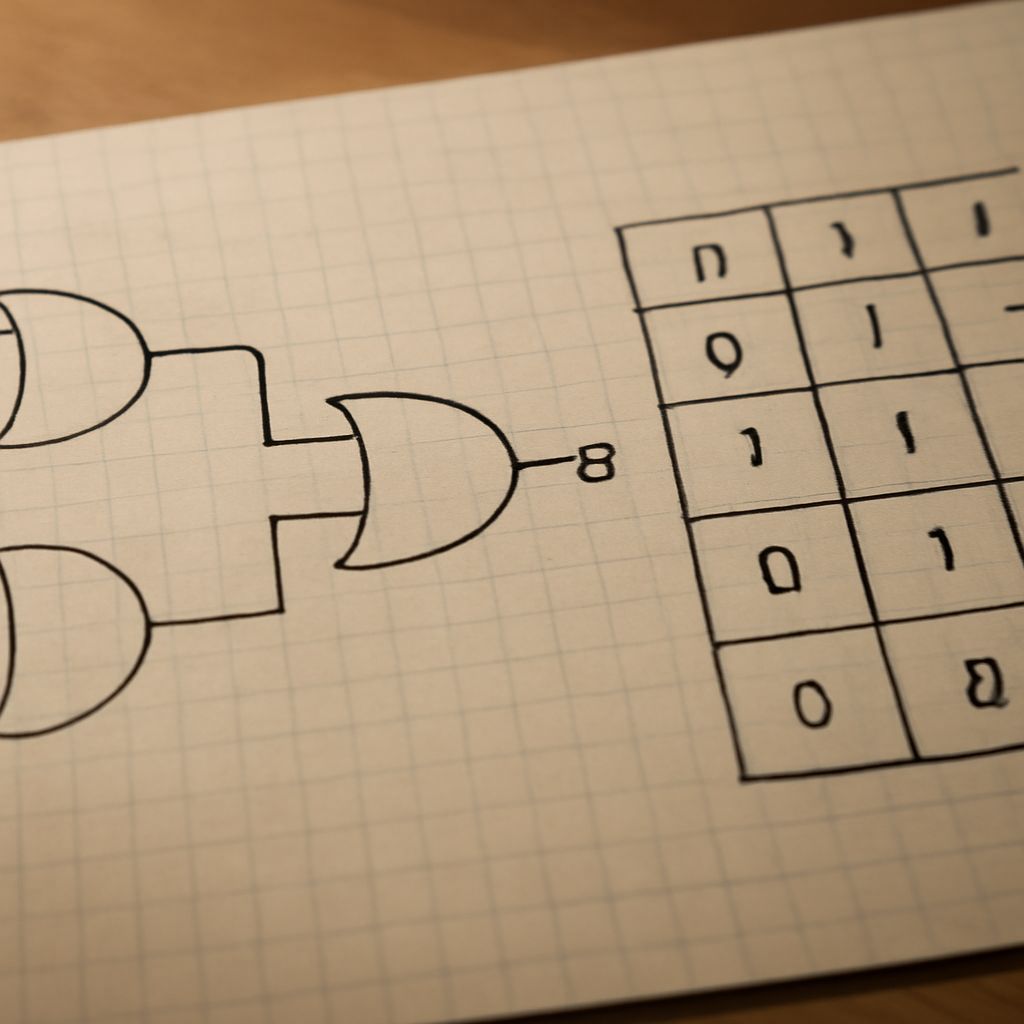
    An XOR gate diagram uses the familiar curved outline of an OR gate, with one important addition: a second curved line appears on the input side, in front of the main gate outline. That extra curve identifies the exclusive function.

    A labeled two-input diagram can be read like this:

    A (input 1) + B (input 2) → XOR gate → Y (output)

    • A and B: the two incoming binary signals.
    • ⊕: the XOR operation between those signals.
    • Y: the output, equal to 1 only when A and B differ.

    For example, compare the bit strings 1011 and 1001 position by position with XOR:

    1011 ⊕ 1001 = 0010

    The 1 in the result marks the position where the input bits differ. Matching bit pairs produce 0, while differing pairs produce 1. The same behavior can toggle a control bit: XOR with 1 changes a bit, while XOR with 0 leaves it unchanged.

  • Truth Tables for Logic Gates: AND, OR, NOT, NAND, NOR, XOR & XNOR

    Truth Tables for Logic Gates: AND, OR, NOT, NAND, NOR, XOR & XNOR

    Truth tables for logic gates show every possible input combination and the resulting output. For a two-input gate, inputs are usually labeled A and B, while the output is Y. A 0 represents false or low, and a 1 represents true or high.

    Read each row from left to right: identify the input values, apply the gate’s Boolean rule, and then check the output column. The complete set of rows makes gate truth tables useful for predicting circuit behavior without inspecting the circuit’s internal design.

    How do you read truth tables for logic gates?

    A two-input truth table has four rows because two binary inputs produce four combinations: 00, 01, 10, and 11. The order of A and B matters when reading a row, even though several basic gates produce the same result when the inputs are swapped.

    • A = 0, B = 0: both inputs are low.
    • A = 0, B = 1: A is low and B is high.
    • A = 1, B = 0: A is high and B is low.
    • A = 1, B = 1: both inputs are high.

    The expression beside a gate states its Boolean operation. For example, Y = A · B means “A AND B.” The output column translates that operation into a result for each row.

    What does a truth table for an AND gate show?

    An AND gate uses the expression Y = A · B. Its plain-language rule is: the output is 1 only when both inputs are 1. Any 0 input makes the output 0.

    • A = 0, B = 0 → Y = 0
    • A = 0, B = 1 → Y = 0
    • A = 1, B = 0 → Y = 0
    • A = 1, B = 1 → Y = 1

    This truth table for an AND gate is the reference for understanding NAND, which reverses the AND output.

    How do OR, NOT, NAND, and NOR gate truth tables work?

    An OR gate uses Y = A + B. Its rule is: the output is 1 when at least one input is 1, including when both inputs are 1.

    • 0, 0 → 0
    • 0, 1 → 1
    • 1, 0 → 1
    • 1, 1 → 1

    A NOT gate has one input and uses Y = ¬A. It inverts its input, so 0 becomes 1 and 1 becomes 0.

    • A = 0 → Y = 1
    • A = 1 → Y = 0

    A NAND gate uses Y = ¬(A · B). It is an AND gate followed by NOT, so its output is the inverse of the AND output: it is 0 only when both inputs are 1.

    • 0, 0 → 1
    • 0, 1 → 1
    • 1, 0 → 1
    • 1, 1 → 0

    A NOR gate uses Y = ¬(A + B). It is an OR gate followed by NOT, so its output is the inverse of the OR output: it is 1 only when both inputs are 0.

    • 0, 0 → 1
    • 0, 1 → 0
    • 1, 0 → 0
    • 1, 1 → 0

    How do XOR and XNOR gate truth tables differ?

    An XOR gate uses Y = A ⊕ B. Its rule is: the output is 1 when exactly one input is 1. XOR is not the same as inclusive OR because XOR returns 0 when both inputs are true.

    • 0, 0 → 0
    • 0, 1 → 1
    • 1, 0 → 1
    • 1, 1 → 0

    An XNOR gate uses Y = ¬(A ⊕ B). It is XOR followed by NOT, so it inverts the XOR output. The output is 1 when the inputs match and 0 when they differ.

    • 0, 0 → 1
    • 0, 1 → 0
    • 1, 0 → 0
    • 1, 1 → 1
  • Hex Subtraction, Addition, and Multiplication in Base 16

    Hex Subtraction, Addition, and Multiplication in Base 16

    Hexadecimal arithmetic uses the same column method as decimal arithmetic, but each column is based on 16. This guide covers hex subtraction, hexadecimal addition, hex multiplication, hexadecimal subtraction, and hexadecimal multiplication with carries, borrows, and decimal checks.

    Align operands by place value, work from right to left, and use the same digit-value map for every operation.

    Hex Digits and Place Values in Base 16

    Hexadecimal uses 16 symbols. The letters continue the values after 9:

    • 0–9: values 0 through 9
    • A: 10, B: 11, C: 12
    • D: 13, E: 14, F: 15

    From right to left, place values are 160, 161, 162, and so on. For example, 2A7 equals 2 × 256 + 10 × 16 + 7. Always right-align operands so units, sixteens, and 256s share a column.

    Hexadecimal Addition With Carries

    In hexadecimal addition, a column produces a carry when its total is 16 or more. Divide the column total by 16: write the remainder in the current column and carry the quotient to the next column. A carry is not made at 10, as it is in base 10.

    A complete addition example with a carry

    Add 2A7 + 19D:

    1. Units: 7 + D = 7 + 13 = 20 decimal, or 14 in hexadecimal. Write 4 and carry 1.
    2. Sixteens: A + 9 + 1 = 10 + 9 + 1 = 20 decimal, or 14 hexadecimal. Write 4 and carry 1.
    3. 256s: 2 + 1 + 1 = 4. Write 4.

    Therefore, 2A7 + 19D = 444. The repeated carries occur because each completed column contains 16 units of the next place value.

    Hex Subtraction With Borrows

    For hexadecimal subtraction, subtract each right-aligned column from right to left. If the top digit is smaller, borrow 1 from the next column. That borrowed 1 equals 16 units in the current column, not 10.

    A hexadecimal subtraction example

    Subtract 1C7 from 3A2:

    1. Units: 2 is smaller than 7, so borrow 1 from A. The units become 2 + 16 = 18, and 18 − 7 = 11, which is B. The A becomes 9.
    2. Sixteens: 9 is smaller than C, so borrow 1 from 3. The column becomes 9 + 16 = 25, and 25 − 12 = 13, which is D. The 3 becomes 2.
    3. 256s: 2 − 1 = 1.

    The result is 3A2 − 1C7 = 1DB. Each borrow adds 16 to the column being solved, while reducing the next column by 1.

    Hexadecimal Multiplication and Decimal Verification

    Hexadecimal multiplication follows long multiplication. Multiply by each digit, convert each product into a hexadecimal digit plus carry, shift each partial product one place for every position moved left, and then add the partial products.

    A hex multiplication example

    Multiply 2F × 1A:

    1. Multiply 2F by A. F × A is 15 × 10 = 150 decimal, which is 96 hexadecimal. Write 6 and carry 9. Then 2 × 10 + 9 = 29 decimal, or 1D hexadecimal. This partial product is 1D6.
    2. Multiply 2F by 1. The partial product is 2F, shifted one hexadecimal place left because 1 is in the sixteens column: 2F0.
    3. Add the partial products: 1D6 + 2F0 = 4C6. In the middle column, D + F = 28 decimal, or 1C hexadecimal; write C and carry 1.

    Therefore, 2F × 1A = 4C6.

    Verify the result in decimal

    Convert the factors and result using powers of 16:

    • 2F = 2 × 16 + 15 = 47
    • 1A = 1 × 16 + 10 = 26
    • 4C6 = 4 × 256 + 12 × 16 + 6 = 1,222

    Now check the multiplication: 47 × 26 = 1,222. The decimal product matches 4C6, confirming the hexadecimal result.

  • Hex to Binary Table: Binary, Decimal, and Hexadecimal Values 0–31

    Hex to Binary Table: Binary, Decimal, and Hexadecimal Values 0–31

    This hex to binary table aligns every integer from 0 through 31 with its eight-bit binary and two-digit hexadecimal form. It also works as a quick binary to decimal chart when you need to verify a value.

    Use the fixed-width columns for lookup, then apply place-value arithmetic or four-bit grouping when converting values beyond the chart.

    Hex to Binary Table: 0–31 Decimal, 8-Bit Binary, and 2-Digit Hex

    Each row follows the order decimal — 8-bit binary — 2-digit hexadecimal. Hexadecimal letters use uppercase notation from A through F.

    • 0 — 00000000 — 00
    • 1 — 00000001 — 01
    • 2 — 00000010 — 02
    • 3 — 00000011 — 03
    • 4 — 00000100 — 04
    • 5 — 00000101 — 05
    • 6 — 00000110 — 06
    • 7 — 00000111 — 07
    • 8 — 00001000 — 08
    • 9 — 00001001 — 09
    • 10 — 00001010 — 0A
    • 11 — 00001011 — 0B
    • 12 — 00001100 — 0C
    • 13 — 00001101 — 0D
    • 14 — 00001110 — 0E
    • 15 — 00001111 — 0F
    • 16 — 00010000 — 10
    • 17 — 00010001 — 11
    • 18 — 00010010 — 12
    • 19 — 00010011 — 13
    • 20 — 00010100 — 14
    • 21 — 00010101 — 15
    • 22 — 00010110 — 16
    • 23 — 00010111 — 17
    • 24 — 00011000 — 18
    • 25 — 00011001 — 19
    • 26 — 00011010 — 1A
    • 27 — 00011011 — 1B
    • 28 — 00011100 — 1C
    • 29 — 00011101 — 1D
    • 30 — 00011110 — 1E
    • 31 — 00011111 — 1F

    Read the Fixed-Width Columns in the Binary to Decimal Chart

    The decimal column shows the ordinary base-10 value. The binary column always has eight positions, while the hexadecimal column always has two digits. Leading zeros preserve that width without changing the value: decimal 5 is binary 00000101 and hexadecimal 05.

    For binary, each position represents a power of two. From right to left, the eight-bit positions are 1, 2, 4, 8, 16, 32, 64, and 128. A 1 means that position contributes to the total; a 0 means it does not.

    Hexadecimal uses sixteen symbols: 0 through 9 represent zero through nine, and A through F represent 10 through 15. This makes each hexadecimal digit equivalent to exactly four binary bits.

    Use the Binary to Decimal Table for Place Values and a Worked Check

    The binary to decimal table can be recreated by adding the place values beneath every 1. Start at the rightmost bit with 1, double each value as you move left, and ignore positions containing 0.

    For example, convert 00010111 to decimal:

    0 × 128 + 0 × 64 + 0 × 32 + 1 × 16 + 0 × 8 + 1 × 4 + 1 × 2 + 1 × 1 = 16 + 4 + 2 + 1 = 23.

    The table confirms the result: decimal 23 is binary 00010111 and hexadecimal 17. The same arithmetic works for any binary length. For a value with more than eight bits, continue the place values to the left with 256, 512, 1,024, and higher powers of two.

    Convert Between Bases with the Binary to Hexadecimal Table Using Four-Bit Nibbles

    For binary-to-hexadecimal conversion, divide the binary number into four-bit groups called nibbles, starting from the right. If the leftmost group has fewer than four bits, add leading zeros. Convert each nibble independently using the values from 0000 through 1111.

    For a value in the chart, convert 00011111:

    00011111 → 0001 1111 → 1F.

    The first nibble, 0001, equals hexadecimal 1. The second nibble, 1111, equals hexadecimal F. Therefore, binary 00011111 equals hexadecimal 1F and decimal 31.

    Reverse the process for hexadecimal-to-binary conversion: replace every hexadecimal digit with its four-bit equivalent and join the groups. For example, hexadecimal D6 is beyond the 0–31 chart:

    D6 → 1101 0110 → 11010110.

    Thus, D6 equals binary 11010110. Its decimal value is 13 × 16 + 6 = 214. Keep all four bits in each nibble, including zeros, so every hexadecimal digit remains aligned with its binary representation.

  • Hello in Binary: How to Encode Greetings as Bytes

    Hello in Binary: How to Encode Greetings as Bytes

    Using lowercase text and ASCII-compatible UTF-8, hello in binary is 01101000 01100101 01101100 01101100 01101111 (ASCII-compatible UTF-8, lowercase “hello”). The answer to how to say hello in binary follows the same letter-by-letter process for every character.

    In this encoding, each lowercase English letter uses one byte, or eight bits. The spaces shown between groups separate bytes; they are formatting and are not part of the word unless a character space is explicitly encoded.

    Hello in binary: What does each byte mean?

    For lowercase hello in ASCII-compatible UTF-8, each character has an ASCII-compatible code point, a decimal byte value, and a padded eight-bit binary value:

    • h — decimal 104 — 01101000
    • e — decimal 101 — 01100101
    • l — decimal 108 — 01101100
    • l — decimal 108 — 01101100
    • o — decimal 111 — 01101111

    The repeated l produces the repeated byte. Because these letters are within the ASCII range, their UTF-8 bytes match their ASCII values.

    How to say hello in binary, step by step

    1. Write the greeting in the intended case: hello, all lowercase.
    2. Separate it into characters: h, e, l, l, and o.
    3. Convert each character to its decimal ASCII-compatible value.
    4. Convert each decimal value to base two and add leading zeroes until every result has eight bits.
    5. Join the bytes in their original order.

    That process creates the binary for hello: 01101000 01100101 01101100 01101100 01101111 (ASCII-compatible UTF-8, lowercase “hello”). Keeping the eight-bit groups visible makes the result easier to check and decode.

    Hi in binary: How does the shorter greeting convert?

    For lowercase hi in ASCII-compatible UTF-8, the character mapping is:

    • h — decimal 104 — 01101000
    • i — decimal 105 — 01101001

    Therefore, hi in binary is 01101000 01101001 (ASCII-compatible UTF-8, lowercase “hi”). It contains two eight-bit bytes, one for each letter.

    Thank you in binary: How is the space handled?

    For lowercase thank you in ASCII-compatible UTF-8, include the space as its own character. Its decimal value is 32, represented by the eight-bit byte 00100000.

    • t — decimal 116 — 01110100
    • h — decimal 104 — 01101000
    • a — decimal 97 — 01100001
    • n — decimal 110 — 01101110
    • k — decimal 107 — 01101011
    • space — decimal 32 — 00100000
    • y — decimal 121 — 01111001
    • o — decimal 111 — 01101111
    • u — decimal 117 — 01110101

    So, thank you in binary is 01110100 01101000 01100001 01101110 01101011 00100000 01111001 01101111 01110101 (ASCII-compatible UTF-8, lowercase “thank you,” including the space).

    If the bytes are written as one continuous sequence, they become 011101000110100001100001011011100110101100100000011110010110111101110101 (ASCII-compatible UTF-8, lowercase “thank you,” including the space). To decode it, start from the left and regroup the bits into sets of eight. Convert each byte back to its decimal value, then match that value to its character. The byte 00100000 becomes the visible gap between thank and you.

  • Two’s Complement: Binary Representation Explained

    Two’s Complement: Binary Representation Explained

    Two’s complement is the standard way to represent signed integers in a fixed number of binary bits. It uses the bit pattern itself to encode positive values, zero, and negative values, allowing the same binary adder to handle signed and unsigned-looking bit patterns.

    This explanation uses an eight-bit word throughout. The two’s-complement binary method connects each pattern to a signed value through positional weights, then uses ordinary binary addition for arithmetic.

    Why does signed binary need two’s complement?

    Bits naturally represent nonnegative values: with eight bits, 00000000 through 11111111 represent 0 through 255 when interpreted as unsigned binary. Signed integers need a way to represent values below zero as well as positive values.

    A signed encoding must also support one representation of zero and practical addition and subtraction. Two’s complement meets these needs without storing a separate sign-and-magnitude field. Every bit contributes to the value, including the most significant bit (MSB), whose weight is negative rather than positive.

    In binary two’s complement, the MSB signals the value range through its weight, but it is not a detachable sign bit attached to an unchanged magnitude. Changing that bit changes the complete numerical interpretation of the pattern.

    How does two’s-complement binary encode values?

    For an eight-bit word, the positional weights are:

    -128, 64, 32, 16, 8, 4, 2, 1

    The leftmost bit has weight -128. Each remaining bit has the familiar positive power-of-two weight. Add the weights of the bits set to 1 to decode the signed value.

    • 00000101 = 4 + 1 = 5
    • 00000000 = 0
    • 01111111 = 127
    • 11111011 = -128 + 64 + 32 + 16 + 8 + 2 + 1 = -5
    • 10000000 = -128

    Positive values have an MSB of 0, while negative values have an MSB of 1. The two’s-complement representation of -5 is therefore 11111011. There is only one zero pattern: 00000000; the system does not need a separate negative zero.

    How does two’s-complement representation support negation and addition?

    To negate a value, invert every bit and add 1, keeping the declared width. This is called invert-and-add-one.

    For example, begin with positive 5:

    00000101 → invert: 11111010 → add 1: 11111011

    Thus, 11111011 represents -5. The process works in reverse as well: inverting 11111011 and adding 1 produces 00000101.

    Once negative values use this encoding, addition remains ordinary binary addition. For example, 5 + (-3) uses:

    00000101 + 11111101 = 1 00000010

    The eight-bit result is 00000010, or 2. The carry beyond the eighth bit is discarded because the word is fixed at eight bits. Subtraction can use the same rule by negating the subtracted value and adding it.

    What range and overflow rules apply to two’s complement in binary?

    An n-bit two’s-complement word represents values from:

    -2n-1 through 2n-1 – 1

    For eight bits, that range is -128 through 127. The range is asymmetric because one bit position has the negative weight -128, while the positive weights add up only to 127.

    Overflow occurs when the exact mathematical result falls outside this fixed-width range. Conceptually, when adding two positive values, a negative-looking result indicates overflow. When adding two negative values, a nonnegative result indicates overflow. Adding operands with different signs cannot overflow.

    For example, 01111111 (127) plus 00000001 (1) produces 10000000, which reads as -128 in eight-bit two’s complement rather than 128. The bit pattern is valid, but the signed result has overflowed. Similarly, -128 plus -1 wraps to the bit pattern for 127, signaling negative overflow.

  • Karnaugh Map: Simplify Boolean Expressions Step by Step

    Karnaugh Map: Simplify Boolean Expressions Step by Step

    A Karnaugh map turns truth-table output values into a layout where adjacent cells represent input combinations that differ in only one variable. By grouping neighboring 1s, you remove variables that change within each group and produce a shorter sum-of-products expression.

    The reliable process is: label the map in Gray-code order, copy each truth-table output into its matching cell, form the largest valid groups, and write one product term for each group.

    How is a Karnaugh map arranged in Gray-code order?

    For three variables, use one variable for the rows and two for the columns. Let A label the rows and BC label the columns:

    • Rows: A = 0 and A = 1
    • Columns: BC = 00, 01, 11, 10

    The column labels use Gray-code order. Each neighboring label changes by one bit, including the transition from the last column, 10, back to the first column, 00. Therefore, the left and right edges are adjacent. The same wraparound rule applies to the top and bottom edges in maps with more row variables.

    Cells that touch along an edge are adjacent. Cells that meet only at a corner are diagonal and are not adjacent. This distinction controls which cells may form a group.

    How do you fill Karnaugh maps from a truth table?

    Start with the truth table’s variable order and match each input combination to its map coordinates. Place a 1 where the function output is 1 and a 0 where it is 0. For example, use this three-variable function with 1s at minterms 0, 1, 2, 4, and 6:

    • BC = 00: row A = 0 has 1; row A = 1 has 1
    • BC = 01: row A = 0 has 1; row A = 1 has 0
    • BC = 11: row A = 0 has 0; row A = 1 has 0
    • BC = 10: row A = 0 has 1; row A = 1 has 1

    The resulting rows are therefore 1 1 0 1 for A = 0 and 1 0 0 1 for A = 1. Keep the labels visible while filling the map; using ordinary binary order such as 00, 01, 10, 11 would incorrectly change the adjacency pattern.

    How does K-map simplification use wraparound, overlap, and power-of-two groups?

    Each group must be a rectangle containing only 1s. Its size must be a power of two: 1, 2, 4, 8, or more cells. Groups may span an edge, and a 1 may belong to more than one group when overlap creates larger or simpler terms.

    In this map, group the two outer columns, 00 and 10, across both rows. They are adjacent through horizontal wraparound, creating a four-cell rectangle. Across this group, A changes and B changes, but C remains 0. This group produces C′.

    The remaining 1 at row A = 0, column BC = 01 can pair with the 1 at column 00 in the same row. That two-cell group overlaps the four-cell group. Within it, A remains 0 and B remains 0, while C changes, so it produces A′B′.

    How do you read the simplified Boolean expression?

    For every group, keep only variables whose values stay constant. Write an uncomplemented variable when it remains 1 and a complemented variable when it remains 0. Omit variables that change inside the group. Then join the retained variables within each term with AND and join the group terms with OR.

    For the example:

    F = C′ + A′B′

    The first term covers all cells where C = 0. The second covers the remaining required 1 where A = 0 and B = 0. This is the result of the Karnaugh-map reduction, with each original 1 covered by at least one valid group.