Author: Amber Colvin

  • XOR Truth Table, Expression, and Gate Diagram

    XOR Truth Table, Expression, and Gate Diagram

    An XOR truth table shows the output of an exclusive OR gate for every possible input combination. The output is true, or 1, when exactly one input is true, or 1. It is false, or 0, when both inputs match: both are 0 or both are 1.

    For two inputs named A and B, the rule is “one but not both.” This rule connects directly to the Boolean expression, the circuit symbol, and practical bit comparisons.

    What does an XOR truth table show about one input but not both?

    An XOR gate has two inputs and one output, commonly written as Y = A ⊕ B. The circled plus sign, ⊕, is the standard Boolean symbol for exclusive OR.

    Use these checks to evaluate the output:

    • If A is 0 and B is 0, neither input is true, so Y is 0.
    • If A is 0 and B is 1, exactly one input is true, so Y is 1.
    • If A is 1 and B is 0, exactly one input is true, so Y is 1.
    • If A is 1 and B is 1, both inputs are true, so Y is 0.

    The last case distinguishes XOR from inclusive OR. An inclusive OR gate produces 1 when both inputs are 1; an XOR gate produces 0 because the inputs are not different.

    How does an XOR logic table list all four input pairs?

    An XOR logic table lists each possible pair once. With two binary inputs, there are 2², or four, combinations. The output column records whether the inputs differ.

    • A = 0, B = 0 → Y = 0: the inputs are equal.
    • A = 0, B = 1 → Y = 1: the inputs are different.
    • A = 1, B = 0 → Y = 1: the inputs are different.
    • A = 1, B = 1 → Y = 0: the inputs are equal.

    This makes XOR useful for detecting disagreement. The output is high only for the two mixed rows, 01 and 10. It is low for the matching rows, 00 and 11. Reading the rows in this order prevents the common error of assigning a true output to the 11 case.

    What Boolean expressions are equivalent to XOR?

    The compact expression is:

    Y = A ⊕ B

    An equivalent AND-OR-NOT expression expands the one-but-not-both rule into two valid paths:

    Y = (A AND NOT B) OR (NOT A AND B)

    The first term is true when A is 1 and B is 0. The second term is true when A is 0 and B is 1. Since either term can produce the output, the two terms are joined with OR.

    In common Boolean algebra notation, the same expression is written:

    Y = A′B + AB′

    Here, the apostrophe means NOT, adjacent variables mean AND, and the plus sign means OR. Some programming and digital-logic contexts use the caret, ^, for XOR, especially in bitwise operations. The surrounding language or circuit notation determines whether that symbol means XOR.

    How do you recognize an XOR gate diagram?

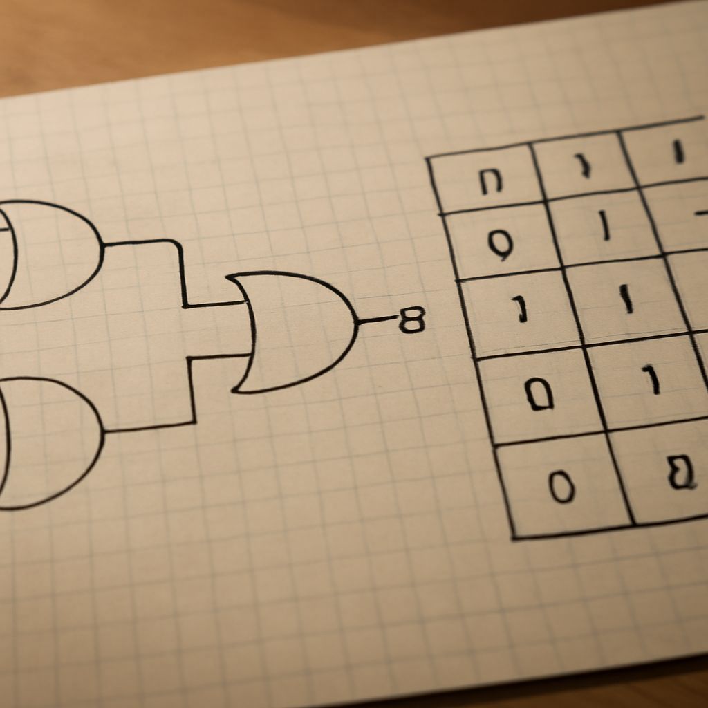
    An XOR gate diagram uses the familiar curved outline of an OR gate, with one important addition: a second curved line appears on the input side, in front of the main gate outline. That extra curve identifies the exclusive function.

    A labeled two-input diagram can be read like this:

    A (input 1) + B (input 2) → XOR gate → Y (output)

    • A and B: the two incoming binary signals.
    • ⊕: the XOR operation between those signals.
    • Y: the output, equal to 1 only when A and B differ.

    For example, compare the bit strings 1011 and 1001 position by position with XOR:

    1011 ⊕ 1001 = 0010

    The 1 in the result marks the position where the input bits differ. Matching bit pairs produce 0, while differing pairs produce 1. The same behavior can toggle a control bit: XOR with 1 changes a bit, while XOR with 0 leaves it unchanged.
  • Truth Tables for Logic Gates: AND, OR, NOT, NAND, NOR, XOR & XNOR

    Truth Tables for Logic Gates: AND, OR, NOT, NAND, NOR, XOR & XNOR

    Truth tables for logic gates show every possible input combination and the resulting output. For a two-input gate, inputs are usually labeled A and B, while the output is Y. A 0 represents false or low, and a 1 represents true or high.

    Read each row from left to right: identify the input values, apply the gate’s Boolean rule, and then check the output column. The complete set of rows makes gate truth tables useful for predicting circuit behavior without inspecting the circuit’s internal design.

    How do you read truth tables for logic gates?

    A two-input truth table has four rows because two binary inputs produce four combinations: 00, 01, 10, and 11. The order of A and B matters when reading a row, even though several basic gates produce the same result when the inputs are swapped.

    • A = 0, B = 0: both inputs are low.
    • A = 0, B = 1: A is low and B is high.
    • A = 1, B = 0: A is high and B is low.
    • A = 1, B = 1: both inputs are high.

    The expression beside a gate states its Boolean operation. For example, Y = A · B means “A AND B.” The output column translates that operation into a result for each row.

    What does a truth table for an AND gate show?

    An AND gate uses the expression Y = A · B. Its plain-language rule is: the output is 1 only when both inputs are 1. Any 0 input makes the output 0.

    • A = 0, B = 0 → Y = 0
    • A = 0, B = 1 → Y = 0
    • A = 1, B = 0 → Y = 0
    • A = 1, B = 1 → Y = 1

    This truth table for an AND gate is the reference for understanding NAND, which reverses the AND output.

    How do OR, NOT, NAND, and NOR gate truth tables work?

    An OR gate uses Y = A + B. Its rule is: the output is 1 when at least one input is 1, including when both inputs are 1.

    • 0, 0 → 0
    • 0, 1 → 1
    • 1, 0 → 1
    • 1, 1 → 1

    A NOT gate has one input and uses Y = ¬A. It inverts its input, so 0 becomes 1 and 1 becomes 0.

    • A = 0 → Y = 1
    • A = 1 → Y = 0

    A NAND gate uses Y = ¬(A · B). It is an AND gate followed by NOT, so its output is the inverse of the AND output: it is 0 only when both inputs are 1.

    • 0, 0 → 1
    • 0, 1 → 1
    • 1, 0 → 1
    • 1, 1 → 0

    A NOR gate uses Y = ¬(A + B). It is an OR gate followed by NOT, so its output is the inverse of the OR output: it is 1 only when both inputs are 0.

    • 0, 0 → 1
    • 0, 1 → 0
    • 1, 0 → 0
    • 1, 1 → 0

    How do XOR and XNOR gate truth tables differ?

    An XOR gate uses Y = A ⊕ B. Its rule is: the output is 1 when exactly one input is 1. XOR is not the same as inclusive OR because XOR returns 0 when both inputs are true.

    • 0, 0 → 0
    • 0, 1 → 1
    • 1, 0 → 1
    • 1, 1 → 0

    An XNOR gate uses Y = ¬(A ⊕ B). It is XOR followed by NOT, so it inverts the XOR output. The output is 1 when the inputs match and 0 when they differ.

    • 0, 0 → 1
    • 0, 1 → 0
    • 1, 0 → 0
    • 1, 1 → 1
  • Hex Subtraction, Addition, and Multiplication in Base 16

    Hex Subtraction, Addition, and Multiplication in Base 16

    Hexadecimal arithmetic uses the same column method as decimal arithmetic, but each column is based on 16. This guide covers hex subtraction, hexadecimal addition, hex multiplication, hexadecimal subtraction, and hexadecimal multiplication with carries, borrows, and decimal checks.

    Align operands by place value, work from right to left, and use the same digit-value map for every operation.

    Hex Digits and Place Values in Base 16

    Hexadecimal uses 16 symbols. The letters continue the values after 9:

    • 0–9: values 0 through 9
    • A: 10, B: 11, C: 12
    • D: 13, E: 14, F: 15

    From right to left, place values are 160, 161, 162, and so on. For example, 2A7 equals 2 × 256 + 10 × 16 + 7. Always right-align operands so units, sixteens, and 256s share a column.

    Hexadecimal Addition With Carries

    In hexadecimal addition, a column produces a carry when its total is 16 or more. Divide the column total by 16: write the remainder in the current column and carry the quotient to the next column. A carry is not made at 10, as it is in base 10.

    A complete addition example with a carry

    Add 2A7 + 19D:

    1. Units: 7 + D = 7 + 13 = 20 decimal, or 14 in hexadecimal. Write 4 and carry 1.
    2. Sixteens: A + 9 + 1 = 10 + 9 + 1 = 20 decimal, or 14 hexadecimal. Write 4 and carry 1.
    3. 256s: 2 + 1 + 1 = 4. Write 4.

    Therefore, 2A7 + 19D = 444. The repeated carries occur because each completed column contains 16 units of the next place value.

    Hex Subtraction With Borrows

    For hexadecimal subtraction, subtract each right-aligned column from right to left. If the top digit is smaller, borrow 1 from the next column. That borrowed 1 equals 16 units in the current column, not 10.

    A hexadecimal subtraction example

    Subtract 1C7 from 3A2:

    1. Units: 2 is smaller than 7, so borrow 1 from A. The units become 2 + 16 = 18, and 18 − 7 = 11, which is B. The A becomes 9.
    2. Sixteens: 9 is smaller than C, so borrow 1 from 3. The column becomes 9 + 16 = 25, and 25 − 12 = 13, which is D. The 3 becomes 2.
    3. 256s: 2 − 1 = 1.

    The result is 3A2 − 1C7 = 1DB. Each borrow adds 16 to the column being solved, while reducing the next column by 1.

    Hexadecimal Multiplication and Decimal Verification

    Hexadecimal multiplication follows long multiplication. Multiply by each digit, convert each product into a hexadecimal digit plus carry, shift each partial product one place for every position moved left, and then add the partial products.

    A hex multiplication example

    Multiply 2F × 1A:

    1. Multiply 2F by A. F × A is 15 × 10 = 150 decimal, which is 96 hexadecimal. Write 6 and carry 9. Then 2 × 10 + 9 = 29 decimal, or 1D hexadecimal. This partial product is 1D6.
    2. Multiply 2F by 1. The partial product is 2F, shifted one hexadecimal place left because 1 is in the sixteens column: 2F0.
    3. Add the partial products: 1D6 + 2F0 = 4C6. In the middle column, D + F = 28 decimal, or 1C hexadecimal; write C and carry 1.

    Therefore, 2F × 1A = 4C6.

    Verify the result in decimal

    Convert the factors and result using powers of 16:

    • 2F = 2 × 16 + 15 = 47
    • 1A = 1 × 16 + 10 = 26
    • 4C6 = 4 × 256 + 12 × 16 + 6 = 1,222

    Now check the multiplication: 47 × 26 = 1,222. The decimal product matches 4C6, confirming the hexadecimal result.

  • Hex to Binary Table: Binary, Decimal, and Hexadecimal Values 0–31

    Hex to Binary Table: Binary, Decimal, and Hexadecimal Values 0–31

    This hex to binary table aligns every integer from 0 through 31 with its eight-bit binary and two-digit hexadecimal form. It also works as a quick binary to decimal chart when you need to verify a value.

    Use the fixed-width columns for lookup, then apply place-value arithmetic or four-bit grouping when converting values beyond the chart.

    Hex to Binary Table: 0–31 Decimal, 8-Bit Binary, and 2-Digit Hex

    Each row follows the order decimal — 8-bit binary — 2-digit hexadecimal. Hexadecimal letters use uppercase notation from A through F.

    • 0 — 00000000 — 00
    • 1 — 00000001 — 01
    • 2 — 00000010 — 02
    • 3 — 00000011 — 03
    • 4 — 00000100 — 04
    • 5 — 00000101 — 05
    • 6 — 00000110 — 06
    • 7 — 00000111 — 07
    • 8 — 00001000 — 08
    • 9 — 00001001 — 09
    • 10 — 00001010 — 0A
    • 11 — 00001011 — 0B
    • 12 — 00001100 — 0C
    • 13 — 00001101 — 0D
    • 14 — 00001110 — 0E
    • 15 — 00001111 — 0F
    • 16 — 00010000 — 10
    • 17 — 00010001 — 11
    • 18 — 00010010 — 12
    • 19 — 00010011 — 13
    • 20 — 00010100 — 14
    • 21 — 00010101 — 15
    • 22 — 00010110 — 16
    • 23 — 00010111 — 17
    • 24 — 00011000 — 18
    • 25 — 00011001 — 19
    • 26 — 00011010 — 1A
    • 27 — 00011011 — 1B
    • 28 — 00011100 — 1C
    • 29 — 00011101 — 1D
    • 30 — 00011110 — 1E
    • 31 — 00011111 — 1F

    Read the Fixed-Width Columns in the Binary to Decimal Chart

    The decimal column shows the ordinary base-10 value. The binary column always has eight positions, while the hexadecimal column always has two digits. Leading zeros preserve that width without changing the value: decimal 5 is binary 00000101 and hexadecimal 05.

    For binary, each position represents a power of two. From right to left, the eight-bit positions are 1, 2, 4, 8, 16, 32, 64, and 128. A 1 means that position contributes to the total; a 0 means it does not.

    Hexadecimal uses sixteen symbols: 0 through 9 represent zero through nine, and A through F represent 10 through 15. This makes each hexadecimal digit equivalent to exactly four binary bits.

    Use the Binary to Decimal Table for Place Values and a Worked Check

    The binary to decimal table can be recreated by adding the place values beneath every 1. Start at the rightmost bit with 1, double each value as you move left, and ignore positions containing 0.

    For example, convert 00010111 to decimal:

    0 × 128 + 0 × 64 + 0 × 32 + 1 × 16 + 0 × 8 + 1 × 4 + 1 × 2 + 1 × 1 = 16 + 4 + 2 + 1 = 23.

    The table confirms the result: decimal 23 is binary 00010111 and hexadecimal 17. The same arithmetic works for any binary length. For a value with more than eight bits, continue the place values to the left with 256, 512, 1,024, and higher powers of two.

    Convert Between Bases with the Binary to Hexadecimal Table Using Four-Bit Nibbles

    For binary-to-hexadecimal conversion, divide the binary number into four-bit groups called nibbles, starting from the right. If the leftmost group has fewer than four bits, add leading zeros. Convert each nibble independently using the values from 0000 through 1111.

    For a value in the chart, convert 00011111:

    00011111 → 0001 1111 → 1F.

    The first nibble, 0001, equals hexadecimal 1. The second nibble, 1111, equals hexadecimal F. Therefore, binary 00011111 equals hexadecimal 1F and decimal 31.

    Reverse the process for hexadecimal-to-binary conversion: replace every hexadecimal digit with its four-bit equivalent and join the groups. For example, hexadecimal D6 is beyond the 0–31 chart:

    D6 → 1101 0110 → 11010110.

    Thus, D6 equals binary 11010110. Its decimal value is 13 × 16 + 6 = 214. Keep all four bits in each nibble, including zeros, so every hexadecimal digit remains aligned with its binary representation.

  • Hello in Binary: How to Encode Greetings as Bytes

    Hello in Binary: How to Encode Greetings as Bytes

    Using lowercase text and ASCII-compatible UTF-8, hello in binary is 01101000 01100101 01101100 01101100 01101111 (ASCII-compatible UTF-8, lowercase “hello”). The answer to how to say hello in binary follows the same letter-by-letter process for every character.

    In this encoding, each lowercase English letter uses one byte, or eight bits. The spaces shown between groups separate bytes; they are formatting and are not part of the word unless a character space is explicitly encoded.

    Hello in binary: What does each byte mean?

    For lowercase hello in ASCII-compatible UTF-8, each character has an ASCII-compatible code point, a decimal byte value, and a padded eight-bit binary value:

    • h — decimal 104 — 01101000
    • e — decimal 101 — 01100101
    • l — decimal 108 — 01101100
    • l — decimal 108 — 01101100
    • o — decimal 111 — 01101111

    The repeated l produces the repeated byte. Because these letters are within the ASCII range, their UTF-8 bytes match their ASCII values.

    How to say hello in binary, step by step

    1. Write the greeting in the intended case: hello, all lowercase.
    2. Separate it into characters: h, e, l, l, and o.
    3. Convert each character to its decimal ASCII-compatible value.
    4. Convert each decimal value to base two and add leading zeroes until every result has eight bits.
    5. Join the bytes in their original order.

    That process creates the binary for hello: 01101000 01100101 01101100 01101100 01101111 (ASCII-compatible UTF-8, lowercase “hello”). Keeping the eight-bit groups visible makes the result easier to check and decode.

    Hi in binary: How does the shorter greeting convert?

    For lowercase hi in ASCII-compatible UTF-8, the character mapping is:

    • h — decimal 104 — 01101000
    • i — decimal 105 — 01101001

    Therefore, hi in binary is 01101000 01101001 (ASCII-compatible UTF-8, lowercase “hi”). It contains two eight-bit bytes, one for each letter.

    Thank you in binary: How is the space handled?

    For lowercase thank you in ASCII-compatible UTF-8, include the space as its own character. Its decimal value is 32, represented by the eight-bit byte 00100000.

    • t — decimal 116 — 01110100
    • h — decimal 104 — 01101000
    • a — decimal 97 — 01100001
    • n — decimal 110 — 01101110
    • k — decimal 107 — 01101011
    • space — decimal 32 — 00100000
    • y — decimal 121 — 01111001
    • o — decimal 111 — 01101111
    • u — decimal 117 — 01110101

    So, thank you in binary is 01110100 01101000 01100001 01101110 01101011 00100000 01111001 01101111 01110101 (ASCII-compatible UTF-8, lowercase “thank you,” including the space).

    If the bytes are written as one continuous sequence, they become 011101000110100001100001011011100110101100100000011110010110111101110101 (ASCII-compatible UTF-8, lowercase “thank you,” including the space). To decode it, start from the left and regroup the bits into sets of eight. Convert each byte back to its decimal value, then match that value to its character. The byte 00100000 becomes the visible gap between thank and you.

  • Two’s Complement: Binary Representation Explained

    Two’s Complement: Binary Representation Explained

    Two’s complement is the standard way to represent signed integers in a fixed number of binary bits. It uses the bit pattern itself to encode positive values, zero, and negative values, allowing the same binary adder to handle signed and unsigned-looking bit patterns.

    This explanation uses an eight-bit word throughout. The two’s-complement binary method connects each pattern to a signed value through positional weights, then uses ordinary binary addition for arithmetic.

    Why does signed binary need two’s complement?

    Bits naturally represent nonnegative values: with eight bits, 00000000 through 11111111 represent 0 through 255 when interpreted as unsigned binary. Signed integers need a way to represent values below zero as well as positive values.

    A signed encoding must also support one representation of zero and practical addition and subtraction. Two’s complement meets these needs without storing a separate sign-and-magnitude field. Every bit contributes to the value, including the most significant bit (MSB), whose weight is negative rather than positive.

    In binary two’s complement, the MSB signals the value range through its weight, but it is not a detachable sign bit attached to an unchanged magnitude. Changing that bit changes the complete numerical interpretation of the pattern.

    How does two’s-complement binary encode values?

    For an eight-bit word, the positional weights are:

    -128, 64, 32, 16, 8, 4, 2, 1

    The leftmost bit has weight -128. Each remaining bit has the familiar positive power-of-two weight. Add the weights of the bits set to 1 to decode the signed value.

    • 00000101 = 4 + 1 = 5
    • 00000000 = 0
    • 01111111 = 127
    • 11111011 = -128 + 64 + 32 + 16 + 8 + 2 + 1 = -5
    • 10000000 = -128

    Positive values have an MSB of 0, while negative values have an MSB of 1. The two’s-complement representation of -5 is therefore 11111011. There is only one zero pattern: 00000000; the system does not need a separate negative zero.

    How does two’s-complement representation support negation and addition?

    To negate a value, invert every bit and add 1, keeping the declared width. This is called invert-and-add-one.

    For example, begin with positive 5:

    00000101 → invert: 11111010 → add 1: 11111011

    Thus, 11111011 represents -5. The process works in reverse as well: inverting 11111011 and adding 1 produces 00000101.

    Once negative values use this encoding, addition remains ordinary binary addition. For example, 5 + (-3) uses:

    00000101 + 11111101 = 1 00000010

    The eight-bit result is 00000010, or 2. The carry beyond the eighth bit is discarded because the word is fixed at eight bits. Subtraction can use the same rule by negating the subtracted value and adding it.

    What range and overflow rules apply to two’s complement in binary?

    An n-bit two’s-complement word represents values from:

    -2n-1 through 2n-1 – 1

    For eight bits, that range is -128 through 127. The range is asymmetric because one bit position has the negative weight -128, while the positive weights add up only to 127.

    Overflow occurs when the exact mathematical result falls outside this fixed-width range. Conceptually, when adding two positive values, a negative-looking result indicates overflow. When adding two negative values, a nonnegative result indicates overflow. Adding operands with different signs cannot overflow.

    For example, 01111111 (127) plus 00000001 (1) produces 10000000, which reads as -128 in eight-bit two’s complement rather than 128. The bit pattern is valid, but the signed result has overflowed. Similarly, -128 plus -1 wraps to the bit pattern for 127, signaling negative overflow.

  • CSS Versions: CSS1, CSS2, and the CSS3 Release Timeline

    CSS Versions: CSS1, CSS2, and the CSS3 Release Timeline

    CSS versions are best understood as a standards timeline, not as a sequence of software packages. CSS1 became a W3C Recommendation on 17 December 1996, and CSS2 followed on 12 May 1998. After CSS2, the specification model changed: CSS3 was divided into separate modules that could advance at different speeds.

    That is why the phrase CSS3 release date is misleading. There is no single date when every feature associated with CSS3 became an official, finished standard.

    CSS versions: CSS1 (17 December 1996) and CSS2 (12 May 1998)

    The major early CSS milestones are:

    • CSS1 — 17 December 1996: The first CSS specification to become a W3C Recommendation. It established core styling features such as fonts, colors, text properties, margins, padding, borders, and basic selectors.
    • CSS2 — 12 May 1998: The second major specification expanded CSS with positioning, media types, generated content, layers, and support for aural presentation.
    • CSS2.1 — 7 June 2011: A revised version of CSS2 that removed, clarified, or corrected features based on implementation experience. It is separate from CSS3.

    CSS1 and CSS2 each represented a broad, coordinated specification. That approach worked for foundational features, but it made the standard difficult to update when different areas were ready at different times.

    When was CSS3 released, and why is there no single date?

    If you ask, “when was CSS3 released,” the accurate answer is that CSS3 did not arrive as one monolithic release. After CSS2, the W3C moved toward a modular structure. Work on early CSS3 modules began around the end of the 1990s, and each module followed its own development and publication path.

    For example, Selectors Level 3, Color Level 3, and Media Queries Level 3 were developed and standardized separately. They did not necessarily reach Recommendation status at the same time, and browser support often appeared before a module was fully standardized.

    Consequently, a date attached to one CSS3 module cannot serve as the release date for all CSS3-era features. Some modules became Recommendations, while others remained working drafts, were revised, or moved into newer levels.

    How did CSS3 modules and levels change the standards model?

    A module covers one area of CSS. Examples include Selectors, Color, Backgrounds and Borders, Transforms, Grid Layout, and Media Queries. Each area can be edited, tested, implemented, and standardized without waiting for every other CSS feature to be complete.

    A module’s level identifies its revision or scope. Selectors Level 3 and Selectors Level 4 are successive versions of the Selectors module. The level number does not describe a single global CSS release. One module can be at Level 4 while another remains at Level 3 or advances to Level 5.

    This structure also separates stable features from proposals and revisions. A module may progress from a working draft to a candidate stage and then to a Recommendation, while another module continues through design changes. The standards process therefore reflects the maturity of individual features rather than one all-or-nothing CSS launch.

    What do modern CSS version labels and snapshots mean?

    “CSS3” remains useful as a historical label for the modular era, especially when discussing features such as Flexbox, Grid, transitions, and advanced selectors. It is not a current, unified version number. “CSS4” is likewise usually informal shorthand unless it names a specific module, such as Selectors Level 4 or Color Level 4.

    Modern CSS snapshots provide a different kind of reference. A snapshot collects specifications and feature levels considered part of the platform at a particular point in time. It is a status picture, not a new CSS version that replaces everything before it.

    For current implementation details, identify the individual module and feature. Browser support is tracked feature by feature because specifications, levels, and implementations continue to progress independently.

  • Button onclick versus href: Choose the Right Navigation Element

    Button onclick versus href: Choose the Right Navigation Element

    For a button onclick href comparison, choose the element by its action, not its appearance. Use an anchor with an href when activation takes the user to another URL, document, download, or in-page location. Style that anchor to look like a button. Use a real button when activation performs an in-page action or requires JavaScript to decide what happens.

    This distinction preserves browser behavior. Anchors support link interactions such as opening a destination in a new tab, copying a link address, and following a URL without JavaScript. Buttons communicate an action. A button can trigger navigation with JavaScript, but that does not make it a semantic substitute for an anchor.

    Button onclick versus href: use an anchor for navigation

    An anchor is the correct element when the result is navigation to a known destination. Its href should contain the URL, so browsers, assistive technologies, search engines, and users can identify the destination before activating it.

    Use an anchor for paths such as /about, full URLs, document downloads, email links, and fragment links such as #features. If an HTML button onclick link sends the user to a known URL, replace that pattern with an anchor and style the anchor instead.

    Do not add an href attribute to a button element. The two elements have different semantic roles, even when they share the same visual design.

    Style an anchor with href to look like a button

    Apply button-like CSS to the anchor while keeping its link behavior. The anchor remains discoverable as a destination and can still receive normal browser focus and link commands.

    HTML: <a class=”button-link” href=”/pricing”>View plans</a>

    CSS: .button-link { display: inline-block; padding: .75rem 1rem; border-radius: .35rem; background: #1769aa; color: #fff; text-decoration: none; font-weight: 600; } .button-link:focus-visible { outline: 3px solid #111; outline-offset: 2px; }

    Use sufficient color contrast and preserve a clear focus indicator. A class changes the presentation, not the meaning: this remains a link because it takes the user to another location.

    Use HTML button navigation with onclick for real actions

    Use a button when activation performs an action in the current interface, such as opening a dialog, toggling a menu, applying a filter, or deleting an item. HTML button onclick navigation is appropriate only when the action genuinely needs JavaScript, such as computing a destination after validation or saving state before redirecting.

    Example: <button type=”button” onclick=”location.assign(‘/account’)”>Open account</button>

    location.assign() navigates the current document to the supplied URL and normally adds that destination to the browser history, allowing the user to return with the Back button. The equivalent property form is location.href = ‘/account’; it also navigates the current page and normally creates a history entry. Neither method opens a new tab.

    Set type=”button” when the control sits inside a form and is not meant to submit it. Without that type, a button inside a form defaults to submission. If JavaScript is unavailable and the destination is known in advance, prefer an anchor so navigation still works.

    Choose by action, not appearance

    • Navigate to a URL, document, download, or page section: use an anchor with href.
    • Open, close, toggle, filter, select, or delete within the page: use a button.
    • Send form data through the form’s normal process: use <button type=”submit”> or the form’s submit control.
    • Navigate only after JavaScript performs a required action: use a button with JavaScript, such as location.assign().

    Choose semantics first, then make the selected element match the interface design. A button-shaped anchor is still navigation; a button with onclick is still an action control.

  • HTML hr tag: Mark a Thematic Break and Style It with CSS

    HTML hr tag: Mark a Thematic Break and Style It with CSS

    The HTML hr tag marks a thematic break between parts of a document. It tells browsers and assistive technologies that the subject, scene, section, or topic has changed; it is not simply a generic decorative line.

    Use an hr element in HTML when the separation has meaning. Use CSS borders on another element when you only need a visual edge around a card, panel, or layout region.

    What does the HTML hr tag represent?

    The hr element represents a transition within a page. Common uses include separating chapters, dividing sections of an article, or marking a change in topic. Its meaning comes from the document structure, not from its default appearance as a horizontal rule.

    Do not insert an hr after every paragraph or use it as a replacement for all decorative dividers. If removing the line would remove no meaningful separation, a border or background on an existing container is usually the better choice.

    How do you write an hr element in HTML?

    The element is void, so it has no closing tag. Write it as <hr> wherever the thematic break belongs in the content flow.

    HTML: <p>The first chapter ends here.</p> <hr> <p>The next chapter begins here.</p>

    Place the element between the related content blocks, rather than at the beginning or end of an unrelated container. Browsers supply default styling, but that appearance varies by browser and may not match the design.

    How do you control hr width in CSS, height, borders, color, and backgrounds?

    Set the width, remove the browser’s default border, and create a controlled top border for a crisp line:

    Border-based: hr { width: 60%; border: 0; border-top: 2px solid #6b7280; }

    A percentage width is calculated against the containing block’s content width, not the viewport. If the containing block is 800px wide, a 60% rule produces a line that is normally 480px wide. A fixed value such as width: 20rem provides a more consistent measure when the design requires one.

    For a background-based treatment, give the element a height and remove its border:

    Background-based: hr { width: 60%; height: 4px; border: 0; background-color: #2563eb; }

    Use a border when the line should behave like a narrow stroke. Use a background when you need a thicker bar or plan to add effects such as a gradient. The color property alone may not change a browser’s default rule consistently, so set border-color, border-top, or background-color explicitly.

    How do you control alignment and spacing around an hr?

    Center a narrower rule with automatic inline margins and control its surrounding whitespace with the margin shorthand:

    Centered and spaced: hr { width: 60%; margin: 2rem auto; border: 0; border-top: 2px solid #d1d5db; }

    Here, 2rem adds space above and below the thematic break, while auto divides the remaining horizontal space evenly. For separate control, use margin-block: 2rem and margin-inline: auto. Keep the spacing on the rule instead of adding empty paragraphs, so the document retains a clear content structure.

  • HTML Blank Space: How to Add Space in HTML

    HTML Blank Space: How to Add Space in HTML

    To add HTML blank space, first identify what should receive the space. Use CSS margin or padding for layout, a non-breaking space for one intentional gap inside text, and preformatted rules when source spacing or line breaks must survive. Whether the task is described as “blank space HTML” or “empty space HTML,” this choice prevents spacing hacks and keeps the result predictable.

    CSS is the default for separating elements. HTML whitespace controls text rendering; it is not a reliable tool for building page geometry.

    How do you add HTML blank space with margin and padding?

    Use margin to create space outside an element and padding to create space between its content and its border. These are the normal CSS tools for spacing paragraphs, headings, cards, buttons, and sections.

    For example, set p { margin-bottom: 1rem; } to separate paragraphs. Give a panel internal breathing room with .panel { padding: 1rem; }. Margin moves neighboring elements apart, while padding enlarges the element’s interior area and carries its background and border with it.

    For an empty visual region, use a defined layout property such as min-height: 8rem; or suitable padding. Do not create a blank region by inserting multiple spaces into the HTML source.

    Why do repeated spaces collapse in HTML?

    In normal HTML text, browsers collapse consecutive spaces, tabs, and line breaks into a single rendered space. Leading and trailing whitespace may also disappear at an element’s edges. For example, several spaces between two words usually display as one space, regardless of how many appear in the source.

    This behavior keeps source formatting from changing the page layout accidentally. It also explains why pressing the spacebar repeatedly does not create dependable spacing between elements. Apply margin, padding, or another layout rule when the distance must remain consistent across screen sizes.

    When should you use &nbsp; for a blank space in HTML?

    Use the non-breaking space entity, written as &nbsp;, for a specific text-level purpose: keeping adjacent content together so the browser cannot break the line between it. A common example is a number and its unit, such as 10&nbsp;kg, or a title and a short suffix that should remain together.

    A non-breaking space also creates one visible space where ordinary whitespace would collapse. It is appropriate for an intentional typographic gap inside a sentence, but it is not a substitute for CSS layout. Avoid chains of non-breaking spaces to position text, align columns, or create large empty areas. Those spaces become fragile when fonts, content, or viewport sizes change.

    How do pre and white-space values preserve empty space in HTML?

    Use the <pre> element when the content itself depends on its original spaces and line breaks, such as a code sample, text file, or fixed-format output. Content inside this element normally preserves source whitespace and uses a monospace presentation. It can also wrap the content in CSS when long lines need to fit.

    The white-space CSS property gives more precise control when the content should remain in an ordinary element:

    • normal: Collapses spaces and line breaks and wraps text. This is the default behavior.
    • nowrap: Collapses whitespace but prevents the text from wrapping onto another line.
    • pre: Preserves spaces and line breaks but does not wrap lines automatically.
    • pre-wrap: Preserves spaces and line breaks while allowing long lines to wrap.
    • pre-line: Preserves line breaks but collapses repeated spaces.

    Choose pre-wrap for user-entered text where formatting matters but overflow should be avoided. Choose pre-line when submitted line breaks matter but repeated indentation does not.